

DIVIDED INTO FOUR SECTIONS....
GENERATOR TIPS - SEARCHLIGHT
TIPS - SCHEMATICS - GENERAL
INFORMATION
VALVES
The greatest initial concern
should
be valve adjustment which assures adequate valve heat dissipation and
engine
breathing. The intake and exhaust valve gap should be adjusted to .010
for INTAKE and .018 for EXHAUST. With the engine cold, remove the
valve covers which are underneath the exhaust manifold and behind the
carburetor.
The blocks use 1/2" nuts. Use a long thin section open end wrench
which is specially made for adjusting valves. This valve wrench will
fit
the lifter while conventional open end wrenches (7/16" & 1/2") will
fit the jamb nut and tappet. The lifter (two flats) is on the bottom of
the assembly, next is the jamb nut (hexagonal nut) and the tappet is
the
(hexagonal bolt) on top. Between the tappet bolt face and the
valve
stem is the gap to be adjusted. The first valve at either end of the
engine
is an exhaust. The next two are intakes, the next two are
exhausts,
etc., etc. Have a friend turn over the engine by hand (a socket
wrench
on a flange coupling or flywheel bolt works fine) while you watch the
intake
and exhaust valves for a selected cylinder go up and down. Turn the
engine
an additional 90 degrees once both valves are down and seated.
Use a feeler gauge to measure the
exhaust and intake gaps. They will probably be tight. Put the
thin
section valve wrench on the lifter (bottom, two flats) and use another
wrench to loosen the jamb nut (hexagonal nut). You can now turn the
tappet
(hexagonal bolt) to adjust the gap. If you tighten the jamb nut just
enough
to let the tappet turn, you can snug up the jamb nut without moving the
tappet out of adjustment. Repeat this procedure for the remaining
valves,
doing a cylinder at a time.
IGNITION
The standard Kettering ignition
system consists of a coil, condenser (capacitor), distributor, ignition
switch, spark plugs, high voltage ignition wires, low voltage primary
wires
and a battery. The battery should be fully charged. Check the spark
plug
wires for cracks, frays and tight connections at the distributor cap,
spark
plugs and coil. Spark plugs are 7/8 inch - 18 thread. Use Champion UJ6
or J8J plugs. The newer designations for the UJ6 & J8J are
J6C
(normal running) & J8C (hotter plug for low speed operation). All
spark
plugs are gapped to 0.025 inches and the points are adjusted to 0.022
inches
after being filed clean. To adjust the point gap, first remove the
distributor
cap and rotor. Crank the engine with the starter in short bursts until
the points are wide open (point rubbing block on peak of cam). Adjust
the
point gap by loosening the jamb nut and turning stationary point until
a 0.022" feeler gauge just passes through the point gap.
Reassemble
the distributor rotor and cap. To check for spark, remove the coil wire
from the center of the distributor cap and position this loose wire
about
1/32 inch from a head bolt. Crank the engine starter with the ignition
ON and look for a white spark at this 1/32 inch gap. If there is no
spark,
make sure the points are clean and try again. If again there is no
spark,
change the condenser (capacitor) and try again. WARNING: TO AVOID HIGH
VOLTAGE SHOCKS, DON'T HOLD ONTO THE COIL WIRE WHEN CRANKING THE ENGINE.
Another common problem is a short in the low voltage wire which goes
from
the negative side of the coil to the distributor. It usually shorts out
where the wire passes through the distributor body because the
insulating
material has broken down. Replacement parts are hard to find, but
carefully
jerry-rigged electricians tape will work. Some additional preventive
maintenance
includes filing the rotor tip clean, cleaning the inside of the
distributor
cap of any carbon tracks left by the rotor, checking the spark advance
weights (below the distributor point plate) for free movement,
lubricating
the advance weights with a dry spray (e.g.) LPS, WD40, CRC, etc.) and
lubricating
the distributor shaft felt wick (under the rotor) with light machine
oil.
Ignition coils usually fail slowly and will usually give a red spark at
the above cited 1/32 inch head bolt/coil wire gap, instead of a good
white
spark. Both oil filled and epoxy coils can be used with good results.
Please
refer to the following chart when selecting an ignition coil. For
example,
a six volt coil will eventually overheat and reduce its output when
used
with an eight volt battery.
CHECK COIL RESISTANCE
6 Volt Coil 1.6 ohms
12 Volt Coil 3.2 ohms
STARTING UP
Assuming the above steps
regarding
spark plugs, rotor, cap, coil and points have been done, we can now
adjust
the engine. A tachometer/dwell meter is very useful for the
tune-up
procedure. The six (6) cylinder engine should be set for 35 degrees of
dwell angle. If necessary, readjust the points to achieve this dwell
angle.
Accelerate the engine up and down quickly. If the dwell angle varies
more
than four (4) degrees, change the points. This test indicates a weak
point
spring. Loosen the clamp on the bottom of the distributor and run
engine at full throttle. Twist the distributor clockwise and counter
clockwise
until you achieve the maximum RPM. Back off the maximum by 50 RPM by
twisting
in the clockwise direction and tighten the distributor clamp. The
engine
is now timed. If the engine loses power during the season, check the
dwell
angle before changing the timing. Adjust the throttle stop screw
to about 600 RPM . Turn in the low speed jet until the RPM drops.
Back out the low speed jet to 1/4 turn beyond maximum idle RPM.
Readjust
the throttle stop screw to the recommended idle 300 RPM. Your Engine Is
Now Properly Tuned. !!!!
Borg Warner Numbers....
Rotor--D208
Cap- C245
Set points at .022
Dwell = 35 degrees
Advance is 6 degrees at 900 RPM
Note:
Check your dwell setting from time to time. As the
points wear, the dwell will increase.
If dwell goes higher, the engine will start to run
hotter. You may see your exhaust manifold glowing red hot! At
this
point the engine will not be smooth running, and may sound like it is
missing.
This is due to heat in the carburetor boiling the fuel. A vapor lock
condition.
GE Oil Filter & Gasket.
The number is NAPA 5080
Carquest
9080
Oil Filter : Carquest
85802
Wix 51802
Another filter but maybe not available, Baldwin T-307-M
A Wix 51600 will fit if you can
find one.
(These filters listed above are the more modern twist
on type filters that have been used by Larry Boggs)
Extend the Life of the
Generator
Engine by...
Get a strong magnet (old car
speaker magnets work fine).
Then stick one or two on the
oil filter. All metallic garbage will be stuck in the filter as it
passes.
When you chuck the filter, re-use the magnets on the next filter.
If you have an in-line fuel
filter (even plastic ones) do the same thing. Another way is to
lower
a magnet into the fuel tank with a metal cable. Then once a month or
so,
pull up the mag and knock off all the crud. The least messy way
is
the cheap plastic filters and put a magnet on it, then chuck the filter.
The Mr. Gasket Micro Solid State Electric Fuel Pump is designed to replace the original equipment fuel pump on carbureted cars, trucks, industrial and farm equipment, lawn and garden and marine pleasure craft. Works great for fuel transfer systems in gasoline and diesel applications as well as an excellent booster pump for the existing mechanical pump. The Mr. Gasket Micro Fuel Pump provides extreme reliability, fast engine starting in hot and cold weather without vapor locking problems. When installed properly the Mr. Gasket Micro Fuel Pumps will provide a constant fuel supply under all conditions for many years . The Mr. Gasket Micro Pump is self priming to 12" of lift, simple two bolt and two wire installation, built-in pressure relief, and has extremely low amp draw. (average 2 amps at maximum delivery).
Mr. Gasket 42S is a universal design for most import 4 and 6 cylinder carburetor applications. 12 Volt negative ground systems only.
Allied Electronics
Corporate
Headquarters
7410 Pebble Drive
Fort Worth, Texas 76118
Phone: 817- 595-3500
800-433-5700
Order on line here and follow
instructions....
Ohmite
RRS25R
Galco Industrial Electronics
26010 Pinehurst Drive
Madison Heights, MI 48071
800-337-0552
http://www.galco.com/
Part Number RRS25R-OHM
Newark InOne
197 Highway 18 South Suite 205
East Brunswick, NJ 08816
800-463-9275
http://www.newark.com/
Part # 01F7651 or 64K5954
Clean the negative brush every time your replace the negative rod. Since it does not rotate like the positive, it gets dirty faster. The brush will last much longer if kept clean. Next time you are in Wal-Mart pick up a .45 Cal Pistol cleaning rod, and brass brush. This is the perfect length to use to clean the Neg brushes, and the .45 cal brass brush works great. A few passes back and forth, then hit with graphite spray and scrub it again. You can also use a Flex Hone. Attach it ot the end of a drill, and clean the brush right out.
Negative Brush on a GE light If you see the upper part of the brush getting too thin on a GE light, replace the brush. If you don't, the metal gets so thin that the material will not be able to carry the current. As a result, the brush will glow RED HOT, and soon will start to melt. There is no warning, and it happens very fast. It will just happen while you are running the light and start to melt.
Clean your brushes: Use
a Flex-hone to clean your positive and negative brushes. Just
attach
to a drill, spray on a little graphite, and pass through a few times.
Brake Cylinder Flex-Hone - 11mm x 8 In - 180 Grit
Brake Cylinder Flex-Hone - 5/8 x 8 In - 180 Grit
You can get them at some tool stores or on the internet at...
Toolsource.com
11mm
Toolsource.com
16mm - 5/8"
Positive Rotation Gear:
Always be sure your positive rotation gear is greased. Hard
to say what is best.
Here are what some operators have been using.
Copper Anti Seize Lubricant from Loctite good up to 1800 degrees.
http://www.shopatmidway.com/p-3911-copper-anti-seize-lubricant-8-oz-brushtop-bottle.aspx
John Deere Grease, same feel as wheel bearing grease
DUPONT lube with Teflon spray on. The oils burn off with the
high temps, but the teflon doesn't.
On Rainy Nights:
put your carbons inside the light. Some lights have carbon holders
inside
the drum for this. You can also mount a can along side the tower, and
put
your carbons in the can. When the light is on, it it will get hot
enough
to cook out any moisture in the rods.

The easy way to test and align this box is to
remove
your carbon rods.
Adjust your generator to provide 78 volts to
the searchlight.
The control box motor will run, and the negative
feed
ratchet should come to rest in a neutral position and not feed at all.
If voltage goes up or down from 78 volts, it will move the armature in
or out to feed or retract the negative rod. With the gap properly set,
and voltage set at 78 volts, the tension spring should be adjusted to
where
the ratchet fork comes to rest between the feed and retract
gears.
Be sure this fork does not rub on either gear wheel. You can
adjust
the gap between the armature and coil frame by loosening the two screws
on the top of the frame. It pinches a spring metal hinge so you can
move
this metal plate in or out. To adjust he spacing of the armature
and coil, loosen the nut that holds the coil in place and either add or
remove shims that might be there.
Clean your glass!!!: After every night of operation, clean the white powder off your glass. This white stuff is cerium from the carbon rod that is deposited onto the glass at the top near the blower. If it rains, or is damp at night, the moisture will cause the cerium to etch your glass!
Glass Cleaner: To
remove the chemical etching off the glass you can use the Janvil
Glass Restore system.
One operator reported that he had streaking on the
inside his glass.... almost like water channels. It
could
have been from when the mirror was acid washed years ago, and
that
there was splash over onto the glass. It would not come off with
any household chemicals. I bought the product and used it as
directed.
The stuff worked wonderfully. Using only the "glass renew" 90% of
the staining/etching was removed. The tough spots and I used the
scratch
remover and then the glass renew and that took off the tough
stuff.
It looks 100% better.
It is definitely easier doing it with the glass out
and seems to do a better job. Took me about an hour to do the
whole
lamp. Used about 1/3 of the bottle of the "Glass Renew". I highly
recommend it.
Get it here.....
http://www.janvil.com/glass_restoration.htm
Searchlight Mirror Polish.
This is something new. $9.99 for a 2 oz bottle.
This polish removes ALL of it in one cleaning and
is a lot easier that you would expect!
Simply wipe on and polish off. NO WATER OR GLASS
CLEANER
NEEDED !!!
This polish is a NON-ABRASIVE CREAM, one container
is enough to clean a 60 inch mirror 1 - 6 times depending on how bad
and
dirty the mirror(s) is/are. CONTACT:
Ron Peters WhiteGaugeGuy@aol.com
10625 Kingwood Drive
Corpus Christi, TX 78410
(361) 244-0679
GE THERMOSTAT MIRROR
ALIGNMENT
First, if you have a focus
wheel,
make sure the head is all the way forward, and a positive rod is 3/4 of
an inch protrusion from the positive nose cap. The positive rod
should
project on the focal point line of the sight glass.
Place a piece of paper between the positive intermittent feed contacts located under the guard in the lower right had corner of the control box to disable the semi auto feed.
Operate the arc for at
least
ten minutes. While the arc is on, if
your thermostat mirror is in spec or close, it will be noted that the
positive
feed magnet will pickup up an drop out at regular intervals. During
this time, keep an eye on your sight glass to be sure the carbon does
not
burn back to the danger line. If your thermostat
does not cycle the magnet, it could be way out of alignment, the points
in the thermostat could be burnt, and the metal strips will need to be
replaced, or the wire from the thermostat to the control box has a bad
connection.
The positive carbon feed occurs only when the
armature
of the positive feed magnet is picked up. The feed starts when the
armature
picks up and stops when the armature drops out.
After ten minutes of arc
operation,
turn the arc off immediately following the start of a positive feed
cycle.
Measure the projection of the
positive carbon beyond the positive nose cap. If the projection is less
than 3/4 of an inch, loosen the locking bolt to adjust the mirror as
follows...
Turn the mirror adjusting eccentric to move the fork of the mirror mounting bracket toward the lamp. Move the fork only a small amount at a time. Tighten the locking bolt before rechecking the positive carbon protrusion.
Operate the arc for four to five feeding cycles, and then check the projection for the positive carbon again. Repeat the above operations until the positive carbon projection is held at 3/4 of an inch, on the focal line of the sight glass.
In general, if the positive
rod
is not being maintained on the focal point line of the sight glass, and
is behind, then move the mirror a bit toward the arc. If the positive
rod
is maintained beyond the focal point mark, then move the mirror away
from
the arc.
Don't forget to remove the
paper
from the points when you are done testing.
The Semi auto knob should be
adjusted to where the points energize the feed magnet just behind the
thermostat
so the feed does not exceed the focal point line on the sight
glass.
If the thermostat should fail, the semi auto points will take over to
feed
the positive carbon.
Note: if the mirror is moved too far, the
thermostat
will power the magnet to feed all the time.
If you load up a positive carbon with too much
protrusion,
the thermostat may also keep the magnet energized and over feed.
If you loose a blower motor, and it gets really hot
inside, the thermostat will keep the magnet energized and over feed.
The ballast is used to limit current so you can
have
the carbons closer together to arc. It also puts less stress on
the
generator by limiting the current when striking the arc. The
ballast
resistor is also the reason for the drop in voltage between the
generator
and the light. It is not a good idea to run the light without a
ballast.
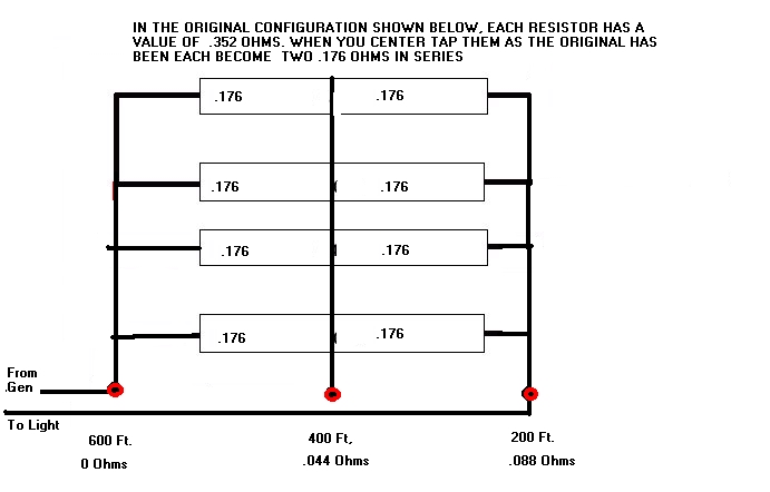
Below is a schematic of how the ballast resistor is
wired in a GE Searchlight.
There are 3 lugs. One for 600 ft, 400 ft, and 200
ft.
cables. There is only one way to correctly connect the ballast
resistor
to a light using short cable less than 200 ft in length, and that is
using
the 600 ft lug and the 200 ft lug. The 600 ft lug is really a common
tie
point where the cable from the generator will always stay. The cable
from
the light can be moved to all three lugs.
Here are the ways you can connect to the ballast and
the results you will get.....
1) The cable that comes in from the generator is always on the 600 ft lug on the far left and wire that goes to the light should be on the 200 ft lug on the far right. You will get .088 ohms of resistance.
2) If you attach the wire going to the light to the middle 400 ft lug, you will get .044 ohms of resistance.
3) If you attach the wire going to the light on the 600 ft lug, you get 0 ohms. The ballast is out of the circuit. The resistance of the length of wire becomes the ballast resistor with a total value of .132 ohms of wire resistance.
4) If you put one wire on the 400 ft lug and the other on the 200 ft lug you will get .044 ohms same as #2 above as when 400 ft and 600 ft is used.
In each case above, the length of cable used adds resistance along with the ballast. With the short cables we use to run our lights, we want to connect to the 200 ft lug for .088 ohms. Any less will put more stress on the generator. As it is, we are running with a shorter cables, and therefore less resistance than the light would like to see. With a 200 ft cable the total resistance would be another .088 ohms added to the ballast resistance for a total of 1.76 ohms. So actually, with our short cables, we should be using a ballast resistance of 1.76 ohms. To compensate for our short cables, we use our rheostat to adjust the voltage down from the 115 volts the manual says we should have at the generator to about 93 volts to allow for 78 volts at the light when the arc is on. If we had 200 ft of cable the added resistance would cause a large drop in voltage, and allow us to raise the generator voltage to 115 volts. Again, we actually need a ballast resistor with a value of 1.76 ohms to run with short cables to be in spec. and run our generator voltage up to 115 volts at the generator.
Through the KenCor Electric Equipment company,
they
have come up with a stamped grid resistor to replace the edge wound
type
that GE now uses. The advantage being newer technology, and much
higher durability. They don't have ceramic in them, and they
don't
break the clips, there are no clips. Also, they're duty rated for
200 amps. Exactly the .088 ohms of resistance needed. In
1942,
all GE units had edge wounds, and they're great for installed
applications.
BUT, they don't work well for mobile, and "tailored" vehicles, e.g.
searchlights.
So, the stamped stainless stuff should be much better, and last longer
than the edge wounds. The only disadvantage, if you can call it
that,
is that the box is approx. 3-4 inches taller than the OEM. Takes
3-4 weeks from order time, but can be rushed to 24 hours if necessary.
The unit would be $480 plus shipping.
KenCor Electrical Equipment
3015 East Skelly Drive Suite 103
Tulsa, OK 74105
Tel: 918-745-6066
Fax: 918-747-2747
Attn: Barry Holcombe
Wet Carbons rods do
not work properly in the searchlight. Carbons must be dry.
If your carbon rods get wet, just bake them in the oven to dry
them.
150 C or 300F for an hour or so. They will be
good
as new.
In general, the control box for both Sperry and GE lights are
responsible
for three things...
1) rotate the positive rod
2) feed the positive rod, and maintain the rods position at the
focal point of the mirror
3) feed the negative rod so it maintains a distance from the
positive
rod to give you 150 amps of current.
There is one DC motor that operates at 78 volts in this box that
controls
all of these things.
For all of this to happen, the voltage at the light must be 78
volts
at the light when the arc is on.
Once the arc is on, this voltage can be adjusted at the generator
using the rheostat.
The voltage at the generator will not be the same as at the light
when the arc is in operation.
The generator will be about 93 volts and the light is 78 when the
arc is on.
When the arc is off, both voltages will be the same.
To maintain the positive rod position, there is a thermostat that
controls the positive feed. This thermostat is mounted on the wall of
the
drum just below the control box on a Sperry, and on the GE it is
mounted
on an arm just to the right of the positive feed unit. The light
from the tip of the positive rod is directed, and focused on the
thermostat using a a magnifying glass on the Sperry and a mirror
on a GE light.
Inside the thermostat is a set of bimetal strips with
contacts.
As the positive rod burns down, the position of the light on the
thermostat
will change causing one of the strips to get hot, and bend. This
bending causes the closing the points to actuate the positive feed
coil.
On a Sperry, this coil is mounted on the front of the positive feed
unit
on the burner. On a GE light this coil is mounted in the control box
and
is connected to the positive feeder on the burner by a long control rod.
When the rod is fed back into the focal point position, the bimetal
strip cools a bit and the points open. The rod should be back on the
focal
point line, and stay there until it burns back.. The cycle repeats over
again..
Both Sperry and GE lights have a backup system made up of a
leaf switch that rides on a lobe that is driven by the motor in this
box.
As the the switch rides up, and down on this lobe, the points open and
close. Each time the point close on this switch, it activates the
positive feed coil that allows the positive rod to feed a little bit
forward.
There is an adjustment on this switch that you can set to have it
close the coil for a long time or short time. It should be set so it
just
maintains the positive carbon just behind the focal point line on the
site
glass. In other words it should feed just a little slow so that the
thermostat
kicks in once in a while.
The negative feed, and position is dictated by a voltage coil on
a Sperry and a current coil on a GE light.
The voltage coil on a Sperry is located on the back of the control
box. You can't get to it. This coil senses 78 volts. The coil suspends
a control arm inside the box. If the arc is burning at 78
volts,
the arm does nothing, but if the voltage should change, the magnetic
field
of this coil will either be weaker or stronger causing the arm to raise
or lower causing a ratchet device to engage and drive the rod in or out
as needed.
On the GE light, the negative rod position is dictated by the
current
coil. This coil is located on the upper left hand side of the
box.
All the current going through the arc goes through this coil. The coil
maintains the position of a contact between two points. When the
current is right at 150 amps, the points are suspended between the
points
and nothing happens. If there is a change of current, the points will
move
up or down depending if it senses an increase or decrease in current
which
creates an increase or decrease in the magnetic field suspending the
points,
and feed either the feed or retract magnetic coil on the clutch that
will
move the negative rod in or out until 150 amps are set.
Sperry 1941-A Searchlight see
it here!
Sperry Generator Schematic see
it here!
GENERATOR:
Generator Power: 15 KWV nominal - 16.7 KWV max. (15,000~16,700 watts
D.C.)
Powered By: In line 6 cyl. "Hercules" Flathead Engine
Generator Engine Fuel: Gasoline (can also be run using Kerosene
or Gasohol) 26 gallons
Generator Fuel Consumption: 2.6 Gal per hour
Combined Weight: 6,000 pounds (3 tons, or the weight of 3 Ford
Mustangs
combined!)
Light Source:
The Beam is made by 2 carbon rods, one positive and one negative,
arching within the focal point of a 60 inch
parabolic mirror. The actual light source is only 1 inch in diameter
at the tip of the positive carbon. It is then magnified by the
mirror.
As the rods "burn" they are automatically fed into the arc. The rods
last
approximately 2 hours and then are replaced. The flame that is visible
during the lights operation, is not actually the source of the light,
rather,
it is a by-product, produced as a result of the electricity arching
between
the 2 rods. The flame is the rod slowly burning away as it is fed into
the light. The arc draws 150 amps continuously at 78 volts DC, and
burns
at over 3,000 degrees Fahrenheit. The power is supplied by the D.C.
generator
which was designed specifically for this purpose.
Check out the LIGHTSKY website, a very valuable
“tool”
for the carbon arc operators that helps fight the darksky.org folks.
Hopefully this website will allow searchlight operators
to give “our side” of the story to City Zoning and Council members and
to provide those people with facts, not fiction before banning
searchlights
for the benefit of a few.
http://www.lightskydarksky.org/
FAA RULES AND REGULATIONS REGARDING SEARCHLIGHTS
10-14-2005. A light
operator
had a phone conversation with the Southwest Regional office of the
FAA - Branch 530
The 530 branch of the FAA
covers
operations in:
Texas, Arkansas, Oklahoma, New
Mexico, Louisiana
He spoke with the Regional
Manger,
Mr. Tervino:
Mr. Trevino illustrated
several
things . . .
1. The FAA does not
have
any rules and regulations in regards to the use of 60" GE or Sperry
Searchlights
that are "on the books".
a. There
are NO formal FAA rules and regulations about the use of, ownership or
operation
of 60" Diameter 800,000,000 million candle power searchlights.
b.
The FAA does have rules on the use and operation of Lasers and Laser
Light
shows.
1. See Advisory Circular - Outdoor Laser Operations - 12/30/2004 - AC
No.
70-1
2. Form "Notice of Proposed Outdoor Laser Operation(s) - Form AC-70-1,
FAA Form
7140-1 (4-01)
3. To be used in conjunction with "Laser Configuration Worksheet" sub
part
of FAA Form
7140-1 (4-01)
c. The only
time that the FAA would intercede in the operation of a searchlight
light
source is:
1. If the use of the searchlight jeopardizes on infringes upon
aircraft
or flight operations
directly.
2. The FAA is mainly concerned with the approach to landing or
take
off of aircraft and
the orientation of the Pilot.
2. The FAA recognizes and works with the searchlight operator as they deem them a bona fide business and the FAA operates under a "good neighbor" policy instead of having formal rules and regulations in regards to the operation of searchlights.
3. The FAA requests that the search light operator submit the following information to the FAA prior to operating their searchlight.
a. Fax
in
a "Proposed Operations Statement" - no formal form, but a form created
by the
owner/operator or company operating the search light.
b. Include
approximate location of search light operation, i.e. At the
intersection
of Main
and 4th Ave., Dallas, Texas 75227
c. Include
the hours of operation, i.e. 8:00pm - 12:00 mid-night
d. Include
the date of operation, i.e. 10-15-2005
e. Include
POC or Point of Contact information for the operator on site.
f.
Include Contact Numbers for operator or company.
4. If the form can be
faxed
on or before close of business on the day of the operation the FAA
would appreciate it.
Once the Proposed Operations
Statement has been received the FAA will then make all local airport
and
aviation facilities aware of the operation, day, date and times.
If the operation of the light is in direct conflict with the operation
of any immediate aircraft or air operations in the proposed area, the
FAA
will contact the searchlight owner/operator and discuss the issue
further.
If there is an issue with
the
operation of the searchlight:
1. The FAA may request
a deviation in the location of the use of the searchlight.
2. The FAA may request
that you do not operate the search light at all.
3. The FAA may request
a deviation in the times the searchlight may be operated.
4. The FAA may want to
discuss the angle or directions of operation.
In a worse case scenario the FAA may demand that the searchlight not be operated if it directly affect the operations of any aircraft or air operations. Mr. Trevion did indicate there there are rules and regulations in regards to interference of aircraft operations and though he has never heard of the FAA enforcing any of those rules he said if an searchlight owner/operator refused to work with the FAA and it endangered aircraft or air operations he said if all other options had been exhausted the FAA would then take action.
Mr. Trevino - bottom lined it this way - "it is a common sense issue" we (the FAA) are willing and enthusiastic about working with any searchlight owner/operator but both parties have to subscribe to a common sense attitude and develop a working relationship based upon mutual respect.
POC Information for FAA Regional Office 530
Manager - Mr. Trevino
(817) 222-5595 - direct line
(817) 222-5547 - fax
UPDATE from Operator Brett
Peabody
7/14/2008
Several people in the
advertising
searchlight industry reassured me that operating a searchlight is “not
against the law”. But, I was not completely satisfied with those
comforting words. So I set out to hear from the most
authoritative
source I could find how federal regulations affect searchlight
usage.
I studied Your article on “FAA Regulations of Searchlights” and had a
short
talk with Mr. Trevino, who you mentioned in your article. He told
me that the key contact for searchlight usage is Mr. Steve Rohring in
Washington
DC . Mr. Rohring’s direct number is (202)267-9231.
I spoke with Mr. Rohring today, and he was very helpful. He patiently answered all of my questions and he helped me to understand exactly how FAA regulations apply to searchlights (as you may know, the FAA calls them “high intensity lights” or “HIL’s”). There are apparently no changes to report since your 2005 conversation with Mr. Trevino in FT. Worth . The FAA is still apparently much more concerned about lasers than they are about HIL’s. Nevertheless, Mr. Rohring says that HIL’s are still a serious concern because HIL’s have been mentioned as a factor in several aviation accident reports. Mr. Rohring is currently heading an effort to develop guidelines and advisories specifically written for HIL operators so we will not have to continue to rely on forms and information that are actually intended for laser operators. He said that the project will take a while to complete, maybe up to a year. Until then, he advised that we should continue to report our planned operations for evaluation in the manner described in your article. When Mr. Rohring’s project is completed, the FAA should be able to provide new operators like me with better guidance on how to comply with FAA guidelines. Mr. Rohring did not indicate that there will be any immediate changes in the regulations themselves.
Here’s my understanding of the FAA regulations and guidelines pertaining to HIL’s: HIL use is generally not restricted by federal statute or regulatory law unless the HIL somehow interferes with the safety of the navigable air space (NAS). The most sensitive areas are near airports or near heavy air routes where HIL’s may interfere with pilots’ vision during takeoff, approach, or landing. If there are any reportable “incidents” involving HIL’s, then the FAA and other agencies are authorized to take various enforcement actions. Enforcement actions can be a very bad thing for operators, so we want to avoid reportable “incidents” at all costs. The notice and “objection” processes described in your article are intended to avoid “incidents” and to help keep the NAS safe for air traffic. When we provide prior notice of our HIL operations to Mr. Trevino or to one of the other two coordinators in other regions, FAA does not approve or disapprove our operations; rather, they merely take the opportunity to “object” or “not object” to how we use our lights. Since filing notice is voluntary, we can choose to ignore FAA’s objections, but that would be a really big mistake! I suspect that the penalties are very harsh for operators who cause reportable incidents after disregarding FAA objections. I also suspect that civil liabilities increase dramatically for operators who ignore FAA objections or who never provide any notice at all.
Based on what I learned, I plan on always providing advance notice to the FAA for all my HIL night usage according to the instructions in your 2005 article. I feel that the FAA is very supportive of the searchlight advertising industry, but that support could easily dissolve if the industry fails to comply with FAA’s safety guidelines. If the FAA sees that operators voluntarily follow their recommendations and guidelines, then they may not feel the need to impose new rules to force us into compliance. The whole purpose of these notice guidelines is to help avoid accidents caused by exposure to our lights, so we should not resist the FAA’s efforts to get proper notice. FAA does not apparently want to shut down our operations; they simply want to study our operations in advance and to suggest ways to make the operations safer. FAA might suggest that we adjust the elevation of the light, change our direction, reposition our light, or screen the light in certain directions by using natural or man-made barriers to block exposures. Even within critical range of an airport (10 miles or less) there may still be ways to safely operate our lights.
Mr. Rohring encouraged me to get in contact with Mr. Trevino at the Ft. Worth FAA office and to establish a long-term relationship with him by regularly sending him notices of my planned HIL operations. There are two other regional coordinators that cover other parts of the nation for the FAA. I didn’t get their names, but I think the names are available on the FAA website. Mr. Rohring said that they prefer 30 days prior notice of HIL operations to allow time to do a thorough study of the surrounding airspace. But, shorter notice is sometimes acceptable. Once a particular location is studied, then it may not be necessary to send notice every time we operate at the same area, but that will be at the discretion of the FAA regional coordinator.
If all other operators also do their best to comply with FAA’s voluntary guidelines, then maybe the FAA will let us continue to operate with the freedom that we now enjoy for a long long time. All it would take is a few unsafe “incidents” and the government could restrict the searchlight advertising industry right out of business. So let’s be safe out there!